Following is a complete list of materials required to build the Turtle Kiosk. Each section will call out the materials used in that area.
| Qty | Description | Vendor | Part # |
|---|---|---|---|
| 3.00 | 3/4" Premium White Birch Plywood | Dakota Hardwoods | pw32503905 |
| 0.50 | 0.118" x 48" x 96" Polycarbonate (Lexan) | Regal Plastics | LX903411848961V |
| 0.25 | 0.220" x 48" x 96" Polycarbonate (Lexan) | Regal Plastics | Lexan 9034 .220x48x96 112 CLR |
All of the stock is intended to be cut on a Shopbot CNC Router. The files are available Here. Each file was programmed with x-axis and y-axis 0 being the very corner of the stock. The z-axis 0 should be the top of the material. Each filename starts with the suggested bit to use. The first file to be run should always be ones with mount holes in the name. After the mount holes file is run, screws should be placed in all available holes. Also programmed thickness of each stock is labeled below, you may need to cheat the z axis to adjust for your material. Here are the sequences for each piece of stock.
| Qty | Description | Vendor | Part # |
|---|---|---|---|
| 0.50 | DAP 128-oz Contact Cement Adhesive | Lowes | 41163 |
| 1.00 | Formica Brand Laminate 48-in x 96-in White- Matte Laminate Kitchen Countertop Sheet | Lowes | 446590 |
| 1.00 | Vibrant Green Microdot Laminate 5' x 12' | Lowes | 144739 |
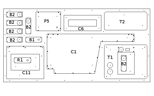
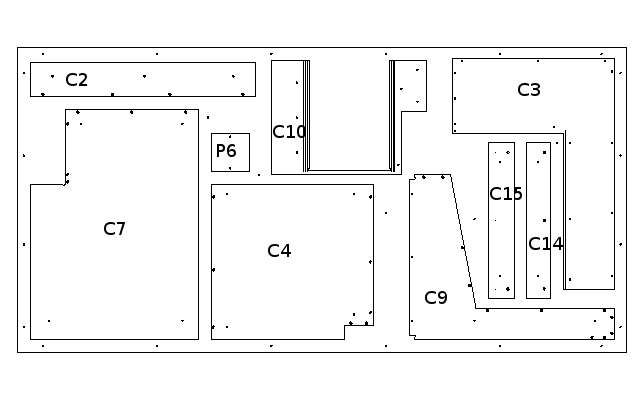
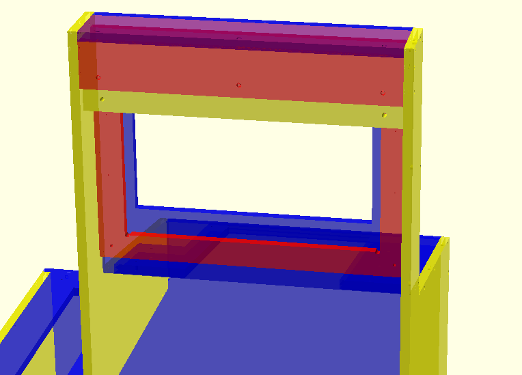
Assemble C1 through C4 as shown in the image below. C3 will need the holes countersunk by hand. Drop C5 in the center and attach then attach C6.
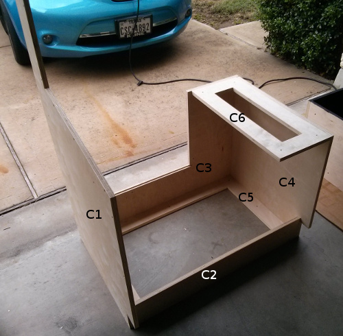
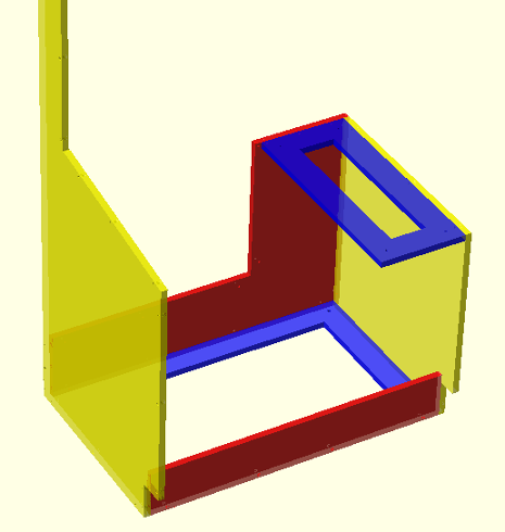
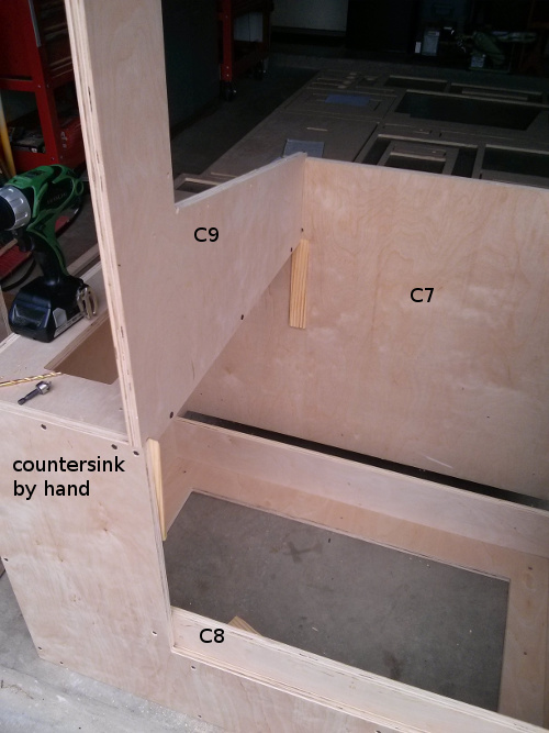
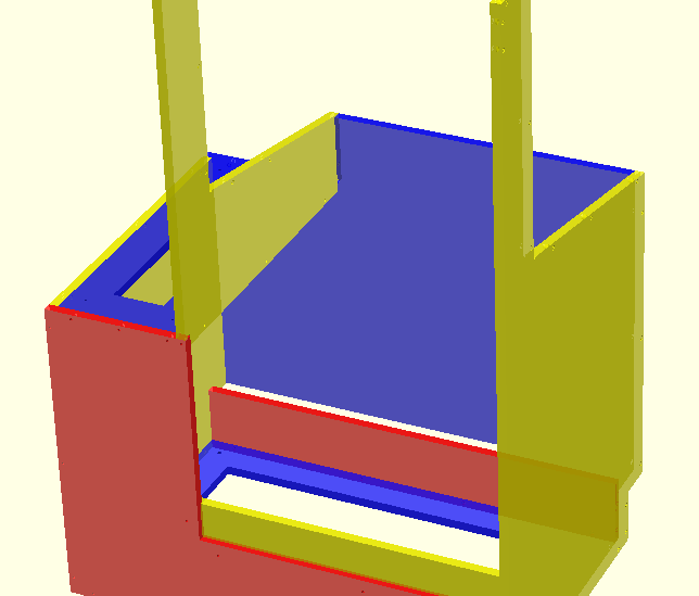
Attach C7 to the front. Attach C8 using the pilot holes as a guide for placement. Finally attach C9 which may require some shims to get the corners to align. This may be better or worse depending on how close your stock was to 3/4".
Attach C10 in the opening, make sure that it is flush with the sides and tight to the front. Attach C11 flush to the top of the cabinet, and finally attach C12.

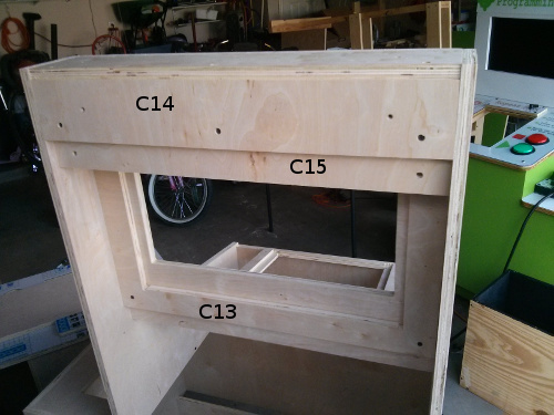
Attach C13 to the back of C11, make sure it's fit tight against C12. Take C14 and C15 and attach them using the pilot holes as a guide. Then attach the C14, C15 assembly to complete assembly.
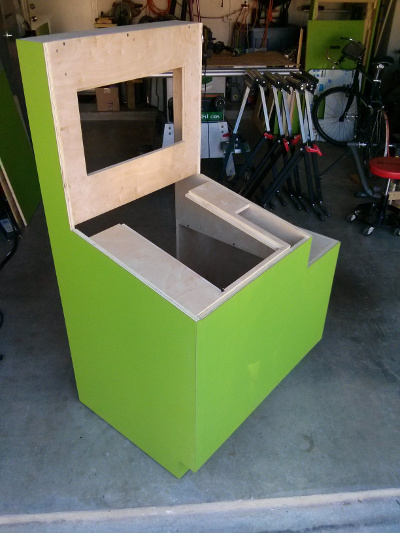
Now that the majority of the cabinet is built it's time to laminate it. Before lamination a flush trim router bit and/or a sander must be used to make all the faces smooth and flat. Also test fit the monitor because it's hard to modify after lamination. The main part of cabinet is intended to be laminated with vibrant green on all faces except C11 and C12. Part D1 is also supposed to be vibrant green.
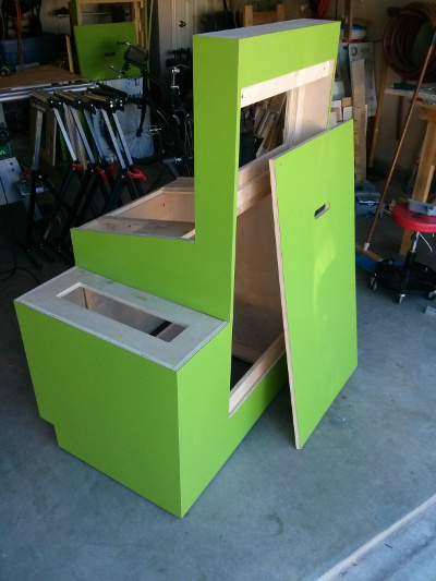
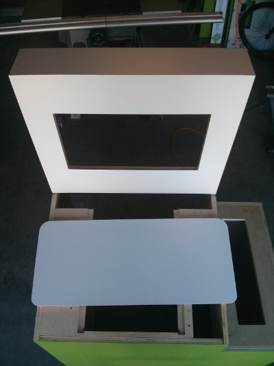
Laminate the cabinet faces of C11 and C12 white. And finally laminate T2 with white.
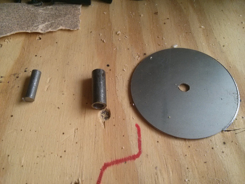
The shaft consists of the 24 gauge steel disk, 3/8" steel rod, and 1/4" steel rod. To cut the disk use a 3" holesaw on the sheet steel. The edges will need to be ground a little to dull them. If you have access to a plasm CNC, the disk can be cut into circles 2 3/4" in diameter with a 1/4" hole in the center for welding. Then cut a 1" length of the 3/8" steel rod and 1" length of the 1/4" steel rod. With a drill-vise drill a 1/4" wide hole a 1/4" deep on 3/8" rod.
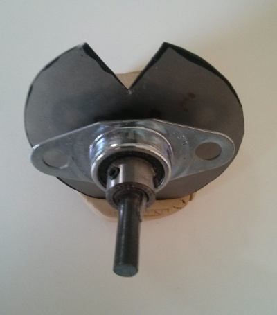
Insert the 1/4" rod into the hole in the 3/8" rod, make sure it sits all the way down in the hole. Weld the shoulder where the two pieces meet. Next place the disk on the 3/8" rod and weld in place. Now we need to do a little grinding to make the top of the disk flat and make sure the entire shaft is less than 3/8" in diameter. Test fit the shaft into one of the bearings to make sure you've sufficiently ground the shaft. Finally we need to notch out a small triangle to give us access to the screws on the bearing use picture below as a guide. Next paint the top of the disk flat black and allow to dry.
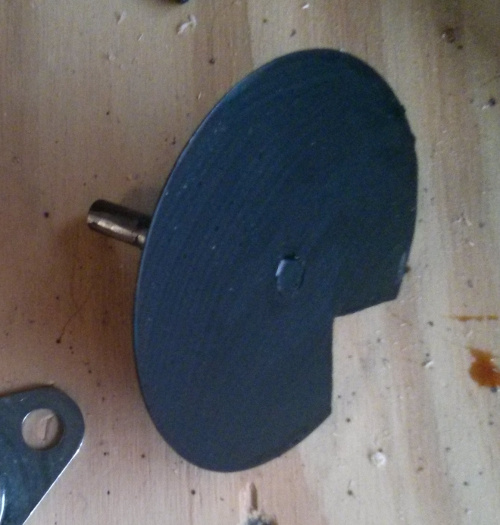
Slide the bearing onto the shaft and tighten it. The bearing should be flush with the joint between the 3/8" shaft and the 1/4" shaft.
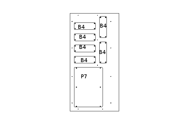
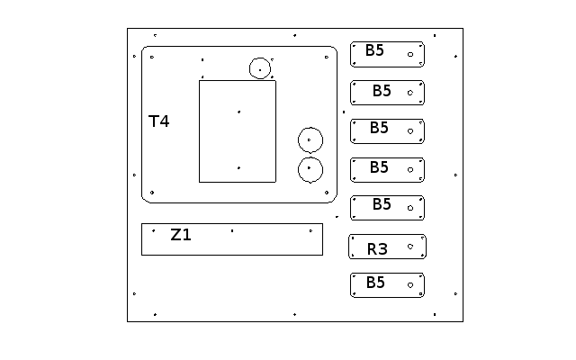
Sand and Poly all of the B1 and B2 pieces, taking care to nicely finish the edges which be exposed in the final product. We also need to sand B3, B4, and B5. With the polycarbonate I prefer to lightly sand with 220 grit and then use a little polyurethane to fill the scratches on the edge. Now take B1 and slide the shaft assembly into it. Secure with two 1/2" #10 screws
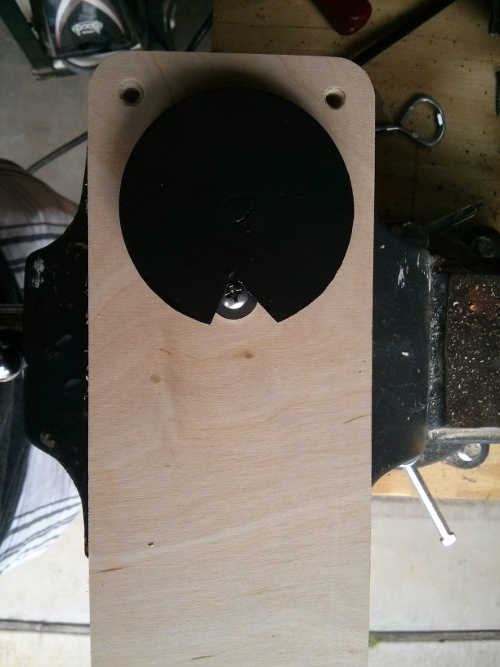
Then apply some contact cement to the shaft disk and then glue one of the octagons from this sheet. Try to make sure that the none of the black shape goes over the notch in the disk. Now place B2 over the top of the shaft disk, followed by B4. Now place the shafts of the binding posts through the assembly.
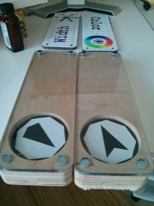
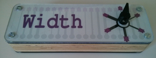
Flip the assembly over and place B5 and B3 over the top of the block and put the bolts in the binding posts. Finally place the indicator knob on the exposed shaft and tighten, making sure to align the arrow of the image underneath with indicator knob. It's a good idea to apply some epoxy to the indicator knob to help with durability.
| Qty | Description | Vendor | Part # |
|---|---|---|---|
| 0.00 | DAP 128-oz Contact Cement Adhesive | Lowes | 41163 |
| 0.10 | Minwax 1-Quart Fast-Drying Semi-Gloss Polyurethane | Lowes | 45871 |
| 0.05 | 100 pack - Tapping Insert for Wood, Hex Drive, with out Flange, 1/4"-20 Interior Thread, 3 | McMaster-Carr | 92105A675 |
| 1.00 | Big Dome Push Button - Red | Sparkfun | COM-09181 |
| 1.00 | Big Dome Push BUtton - Green | Sparkfun | COM-11275 |
| 0.10 | 50 pack - 18-8 Stainless Steel Button-Head Socket Cap Screw, 1/4"-20 Thread, 3/4" Length | McMaster-Carr | 92949A540 |
First we need to sand and finish a few parts. T1 should be finished with polyurethane everywhere and the edges will be exposed in the final product, so sand carefully. T2 will also have exposed edges in the final product so sand and poly them. C11 on the main cabinet will have exposed edges where the monitor will sit, so sand and poly them.
Once T1 is dry, print the black and white symbols for the kiosk, the image can be found here. The image should be printed on 8.5" x 11" paper. The black and white square in the middle should be cut out and be rubber cemented into the hollow on T1. Make sure the black side goes to the right.
Once the square is rubber cemented into the hollow of T1, flip it over and place the piece on top of piece C10 of the assembled cabinet. Place screws in the holes of C10 to secure T1.
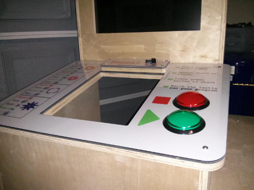
Mount T2 onto C6 and the cabinet should be fully assembled.
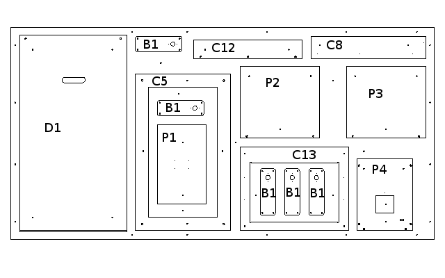
Assemble P1 through P5 as shown in picture and paint all inside surfaces and edges flat black. Start with P1 and add each piece in sequence using the counter sunk holes on each piece as a guide to assembly. Also paint one side of P6 flat black.
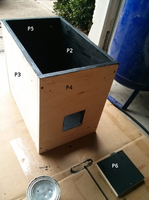
After paint is dry, attach P6 to the assembly with a single screw. P6 is intended to be a loose swinging door for access to the photo chamber after final assembly. Then take the webcam and drill two holes 2" apart in the bottom of the base. Take two screws and mount the camera on the right side of the bottom of the photo chamber. It is important to get the camera on the correct side of the photo chamber or there will be reflection issues in the final product. Put the light bulb sockets in the holes and secure with hot glue. Wire the two light bulbs together and leave a long pigtail on it for attaching to the electronics later. Finally screw the polycarbonate cover P7 onto the assembly.

| Qty | Description | Vendor | Part # |
|---|---|---|---|
| 1.00 | Zotac Intel Core i3-3120M 2.5GHz HM76 4GB DDR3 500GB HDD with Wi-Fi A&V&GbE Mini PC Barebo | Amazon | ZBOX-ID91-PLUS-U |
First step is to install Ubuntu. First download Ubuntu 14.04 LTS at here. Then you need to write the ISO out to a USB key using this process. Then boot up into the USB key and select "Install Ubuntu". Follow the setup guide presented but when you get to the user section, name the user "turtlekiosk" with the password "turtlekiosk" and select the automatic logon at startup option. Please do not select a different password or username, they are not really used for security and recovering them is quite difficult. Also make sure you connect to the internet and get all updates during installation.
Once the computer starts click the ubuntu logo in the top left corner and type "Brightness & Lock" and select the control panel by that name. Inside this control panel, make sure the "Dim screen" option is unchecked. The "Turn screen off when" option should be put to "Never". The "Lock" option should be set to "OFF", and finally the "Require my password when waking" option should be unchecked. Then you can close the control panel.
Click on the ubuntu launcher in the top left corner and type "Software & Updates". Once the control panel is open then click on the "Updates" tab. Inside the updates tab change the "Automatically check for updates:" field to "Never".
Now open a terminal by clicking on the launcher icon and typing "Terminal". Once open type the following command "sudo apt-get install python3-serial python3-opencv python3-pip" It will prompt you for your password and then ask if you are sure, type "y". Once that operation is complete type "sudo apt-get install git git-gui v4l-utils uvcdynctrl". Also execute "pip3 install pygame". Now let's pull down the software. On the command line type "git clone https://[your username]@bitbucket.org/messelman/turtle_pygame.git ./turtlekiosk", note that the your username needs to be replaced by your own username. The last thing we need to do in the terminal is set up for a nightly reboot. In the terminal type "sudo crontab -e", it will ask for your password which should be "turtlekiosk". Then it will bring you into an editor. At the bottom of the file add the following line: "2 2 * * * /sbin/shutdown -r +5". Finally save your changes with Ctrl+o and then the Enter key, finally exit with Ctrl+x. Once that is complete write the following command on the terminal "sudo adduser turtlekiosk dialout". In the terminal now type "sudo nano /etc/default/apport" This will bring up another editor. In the window change "enabled=1" to "enabled=0" then save the changes with Ctrl+o and exit with Ctrl+x. You can now close the terminal.
Now we're going to set up the auto-start feature for the software. Move the cursor all the way to the left until the menu bar appears on the left side. Click the Ubuntu logo and type "Startup Applications" and enter the control panel. Now click the add button and type the name "turtlekiosk" then browse for the command. The command should be "/home/turtlekiok/turtlekiosk/launch_kiosk". Finally click the "Save" button and close the control panel. We also need to hide the menu bar on the left side of the screen. Click the Ubuntu logo in the top left again and type "Appearance". Click on the control panel and switch to the "Behavior" tab. Click the "On" button for the "Auto-hide the Launcher" feature. Close the menu and the menu bar should disappear. Now reboot the computer by clicking on the gear icon in the top right corner of the computer.
| Qty | Description | Vendor | Part # |
|---|---|---|---|
| 0.20 | 10 pack - Incandescent Light Bulb, Trade Number 194, 0.37" Diameter Wedge Base, 14 Volt | McMaster-Carr | 1505K84 |
| 1.00 | Arduino Stackable header kit - R3 | Sparkfun | PRT-11417 |
| 1.00 | arduino 4x4 driver shield | Sparkfun | DEV-11352 |
| 1.00 | Arduino Uno - R3 | Sparkfun | DEV-11021 |
| 1.00 | Female headers | Sparkfun | PRT-00115 |
| 1.00 | Enclosure for pcDuino/Arduino - Clear | Sparkfun | PRT-11797 |
| 1.00 | Enclosure for pcDuino/Arduino - Extension Plate (Clear) | Sparkfun | PRT-11798 |
| 1.00 | Power Supply - 12V/5V (2A) | Sparkfun | TOL-11296 |
| 1.00 | 4 Pin Molex Connector - Pigtail | Sparkfun | TOL-11298 |
| 0.25 | Hook-Up Wire - Assortment (Solid Core, 22 AWG) | Sparkfun | PRT-11367 |
First screw the Arduino into the bottom of the Arduino case. Then we need to solder the headers onto the 4x4 driver shield. We will not use the headers provided in the 4x4 drive shield kit. We are going to use the Arduino stackable headers that we order separately. Place 3 of the headers in the holes shown in the following picture. Solder the headers onto that board, note that this shield is harder than most to solder because it doesn't transmit heat like normal.
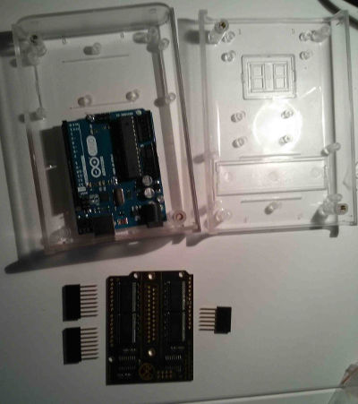
Next we need to put some female 0.1" headers in the center of the 4x4 driver shield. These headers need to have short solder leads on the bottom, not the long ones like the arduino stackable headers. We need to cut a 3 hole piece and a 2 hole piece of the headers. The 3 hole header needs to be soldered to pins 1-3 in the center of the 4x4 driver shield. The 2 hole header needs to be soldered to pins 5-6 of the 4x4 driver shield. The 4x4 driver shield can now be stacked onto the arduino in the case and firmly pressed completely down.

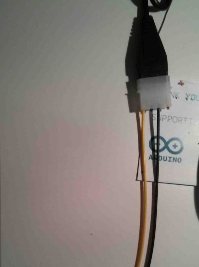
Next grab the molex connector and trim off the extra ground and the 5V power wires right down to the connector. The unused ground should be the black wire next to the yellow wire. The 5V line should be the red wire. Once they are both trimmed the pigtail should look like this.
Now comes the tricky part of making the wire harness. First let's take some male to male headers and cut an 8, 6, 3, 2 long segments. Then we cut 2 yellow pieces of wire 12" long and 1 red wire 12" long. We take these wires and strip the ends and cut 3 heat shrink segments to cover the soldered ends. Now solder the first yellow wire onto pin 2 of the 8 pin header. Solder the other yellow wire to pin 4. Finally solder the red wire onto pin 5 as shown below near number 1.
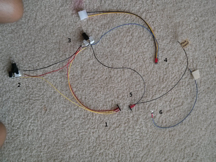
Take the micro switch out of the red push button switch and put a 3 watt light bulb in it. Then cut 8" lengths of red and black wire. Take yellow wire from pin 2 of step 1 and solder it onto the common tab of the microswitch. Solder the red wire onto the NO tab of the switch. Solder the black wire onto the NC tab of the switch. This is shown in the above image near the number 2.
Take the switch out of green push button and put a 3 watt bulb in it. Now cut a 2" and a 12" segment of black wire and cut a 12" segment of blue wire. Now take the black wire from step 2 and the 2" black wire and solder them onto the NC tab of the switch. Take the red wire from step 2 and the red wire from step 1 and solder them onto the NO tab of the switch. Then take the remaining yellow wire from step 1 and solder it onto the common tab of the switch. Then take the remaining end of the 2" black wire and the 12" black wire and solder it onto one of the side tabs of the switch. Finally solder the blue wire onto the other side tab of the switch.
Take the 3 pin header and solder the blue wire from step 3 onto pin 1 with heat shrink tubing. Then solder the yellow wire from the molex connector onto pin 2 and solder the black wire from the molex connector to pin 3.
Take the 6 pin male to male header and solder the black wire from step 3 to pin 2 of the connector. Now cut another 12" piece of wire and solder it to pin 3 of the connector.
Cut a 12" piece of blue wire and solder one end to the 2 pin male to male header.
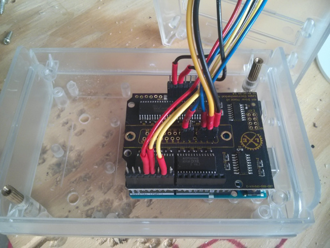
Now take the top cover of the arduino case and leave the 1" square opening open on the top. Slide each of the headers through the opening in the case and place them according to the picture below. Then screw the cover onto case with the switches and remaining wires hanging out of the case.
First you'll need to download the Arduino Software suite here. Once you have the software downloaded and installed you need to download the arduino code here. Create a folder in your sketchbook named "turtle_arduino" and copy the arduino software files into that folder. You will also need to download and install this arduino library on you system. Once you have the program and the library installed, you can launch the arduino software and open the "turtle_arduino" sketch in your sketchbook. Then connect the arduino to your computer via USB cable and click the "Upload" button in the arduino IDE. If no errors are reported then the arduino is complete.
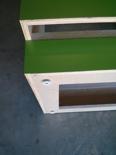
Turn the cabinet over and insert the flange nuts into the 4 corners of C5. Then screw in the feet into each flange nut.
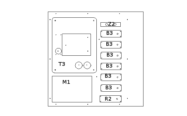
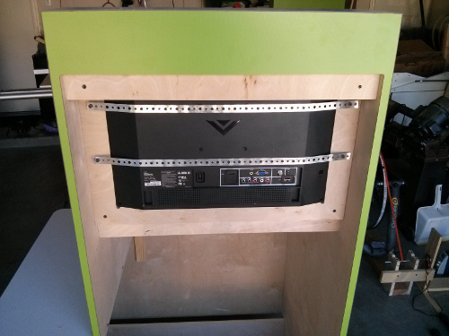
Take M1 and insert it into the monitor hole from the back. Then place the Monitor into the slot. Make sure both the plastic and monitor are pushed all the way to the front. Cut 2 strips of plumbers straping long enough to span the pilot holes on C13. Then screw the straping to C13 making sure that it tightens the monitor into place.
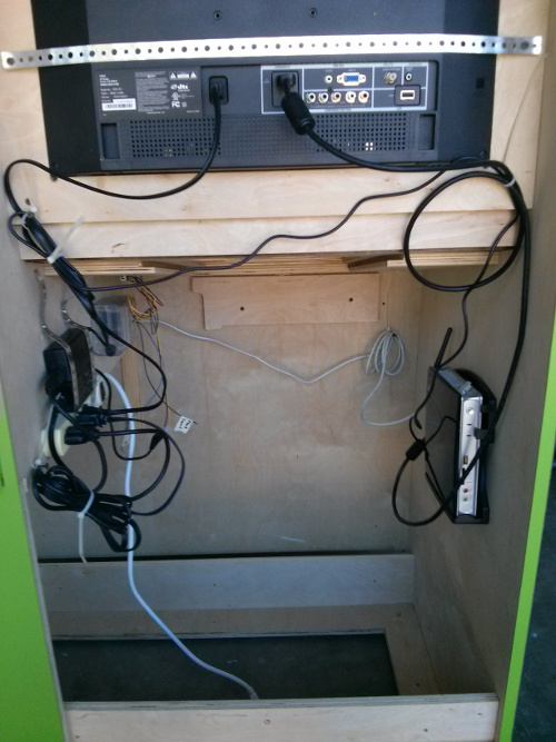
Now we need to mount all the electronics inside the cabinet. Start by screwing the PC mount to the right inside the cabinet as viewed from the back. Then screw the Arduino assembly up close to the buttons, so the button switches can be connected. Insert the button switches into the button housing, the green button should be the switch with the 5 wires connected. Now use plumbers strapping to secure the power strip and transformers to the left side in front of the arduino. Plug in the PC transformer, Arduino Transformer and the monitor to the power strip. Connect a USB cable between the arduino and the PC. Connect the HDMI cable between the monitor and the PC. Connect the arduino transformer to the arduino. Finally use cable holder to strap all the wires around the edges. Make sure you leave the center section open so you can slide the photobox into the assembly.
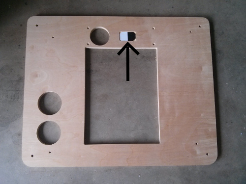
We need to drill through the laminate for the 3 holes that are near the top of C11. I used a stepped drill bit to locate the holes and then a counter sinking bit over cut the laminate. The holes are all 1" from the top. Two of the holes are 1.75" from each edge and the final one is directly in the center. It is all right if the holes are not perfectly pretty because it will get covered up by Z1. Now put 1/4 - 20 inserts into these three holes and attach Z1 using 3/4" bolts.
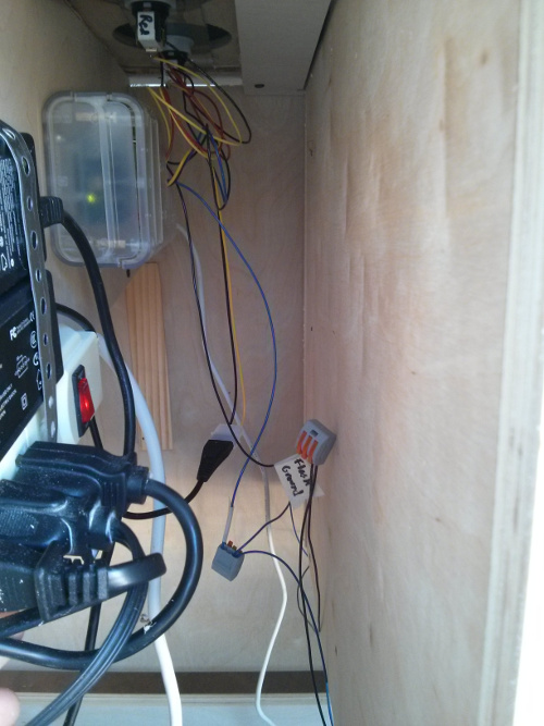
Slide the Photobox assembly into the slot made between C10 and T1, make sure the door of the photobox is facing the rear. Now fish the webcam cable out of the box and plug it into the computer. Now take the flash blub wires and join to the arduino assembly using Wago connectors.
Insert two 1/4 - 20 inserts into the larger holes on C15. On D1 we need to drill holes through the laminate where the mount holes are the top two corners. A scrap piece of wood should be firmly clamped onto the laminate side of the door and then drill through the holes from the back with a 11/32" drill bit. Slide the door into the groove on the bottom of the cabinet opening then place two 1" bolts in the top corners.
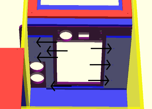
If you have not rebooted the computer after the Computer Preparation section do so now and the turtlekiosk software will start automatically. Once the software is running, move the mouse all the way to the left of the screen and the menu bar should pop up. Click on the file cabinet icon and double click the "turtlekiosk" folder then the "kiosk" folder. In here should be able to double click the "camera_config.txt" file, we're going to leave this file open through the next few steps. Edit the line "DEBUG_SAVE_IMAGE = 0" to read "DEBUG_SAVE_IMAGE = 1" and save the file. Now press the green button and a file named "cvoutput.png" should appear in the folder "turtlekiosk". Open that image by double clicking it. Then arrange your screen as shown below.
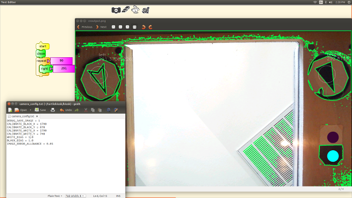
Now we start the calibration procedure by placing one block on the bottom of the table and pressing the green button. We need to adjust the camera position with our hands until we can see both the repeat block at the right of the image and the other block on the left. Once we have the right framing for the camera, then we need to adjust the calibration circles. The calibration square is the black and white box on the right bottom side of the image. The calibration circles are the pale blue circle and dark purple circles drawn on the image. We need to adjust the pale blue dot to be in the black square, and the dark purple circle to be in the white square. These can be adjusted by changing the values in "camera_config.txt" by changing the "CALIBRATE_BLACK_X" and "CALIBRATE_BLACK_Y". Keep in mind that x-axis is left to right and 0 to 1920 respectively. The y-axis is top to bottom and 0 to 1080 pixels. You can adjust these positioning values and resave the camera_config.txt file then click the green button. Continue adjusting values, saving the file, and hitting green button until the circles are in the correct position. Once the calibration circles are over the correct calibration square then you should see the markup on the block images for proper detection of the blocks. Finally before exiting we need to turn off the debugging by setting "DEBUG_SAVE_IMAGE = 0" and save the configuration file. Now reboot the computer and everything should be operating correctly.
The following paragraph is very advanced and should only be required if a camera other than the one listed in the BOM is used. These notes are kept to help recalibrate a new camera when the standard camera becomes unavailable. The program v4l2ucp is used to alter the camera settings. The focus and exposure need to be fixed to make sure the camera focuses on the blocks not the ceiling or someones face. The exposure needs to be fixed to make sure any open area in the cameras field of view isn't washing out the image. To preview the camera use the command qv4l2. Any settings adjustments made with v4l2ucp will instantly take effect on the image shown in qv4l2.